
Tip: As you disassemble, take lots of pictures — they’ll be invaluable when it comes time to put everything back together.
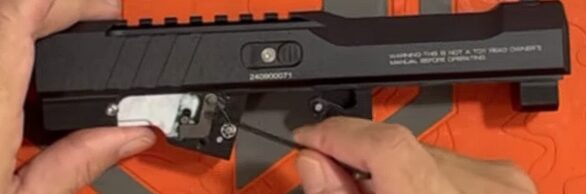
1 Remove the Lower
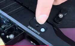
There are two screws holding the lower in place — one at the front of the frame and one at the back. Remove both screws, being careful to retain the washers, and set them somewhere safe.
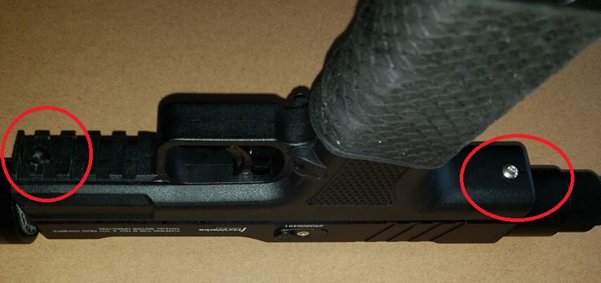
The two screws — front and back — that secure the lower to the upper.
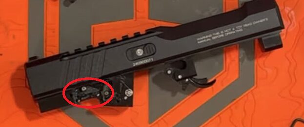
Once both screws are out, pull the lower away from the upper. There is a trigger bar inside — keep your finger on it as you pull, because it can pop out quickly.
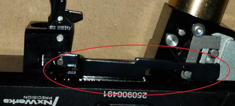
Keep your finger on the trigger bar as you separate the lower — it will pop out if unsupported.
- Steel ball area — air bypassing the ball valve internally.
- Side valve port — O-ring on the internal side valve needs replacement.
- Center barrel — main valve O-ring.
Once you’ve identified the leak, discharge all remaining air before continuing.
2 Remove the Back Valve Assembly
Using an allen wrench, remove the back valve (if you have a tuning adapter, unscrew it by hand). The entire back piston assembly comes out as a unit — set it aside for O-ring identification later.
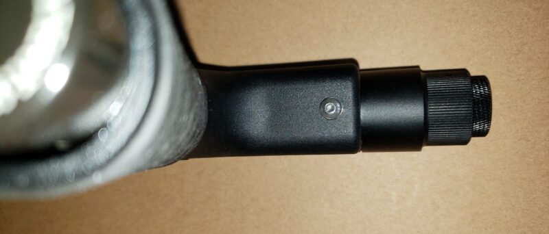
The back valve assembly removed as a single unit.
3 Remove the Sear Assembly
There are two screws securing the main sear cover plate. Remove both, pull out the small lever, and lift the entire plate away. Inside you’ll see the sear — the primary mechanism that fires the unit.
To access the main spring-rest valve, pull the sear out completely. Remove the pin that holds the lower sear first, then pull the sear free.
With the sear removed, pull the main valve out from the body. There is an O-ring seated directly behind the spring-rest valve — note its exact position before removing it.
The spring-rest valve with its O-ring — note the position carefully before removing.
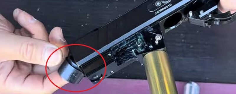
4 Ball Detent Cover (if needed)
The small cover on the side of the upper houses the ball detent — the steel ball that keeps ammunition from rolling out of the breech. You almost never need to open this, but if a ball is damaged or lost, it’s a simple fix: remove the cover, lift the spring, swap the ball, replace the cover centered, and screw it back down.
The ball detent cover — rarely needs servicing, but straightforward when it does.
5 Greasing and Maintenance Notes
Most internal components come pre-greased from the factory. After several thousand shots, it’s good practice to:
- Apply a small amount of the included grease to all O-rings before reinstalling.
- Add a drop of oil into the bolt/pin area to keep the pin moving freely and prevent the O-ring behind it from drying out.
6 Reassembly
Reassemble in reverse order, following these steps carefully:
- Drop the main valve assembly back into the body, seating it fully at the bottom of the channel.
- Reinstall the sear — remove the pin temporarily, place the sear back, reinstall the spring, reinsert the pin, then install the second larger pin to lock the assembly.
- Compress the sear — push it down and forward to expose the spring pin hole, then insert the pin to hold the cocked position.
- Replace the cover plate — line it up and reinstall both screws.
- Check the trigger bar spring — this small spring can slip out of position as the upper and lower come back together, preventing the trigger from resetting. If the trigger doesn’t return after assembly, check here first.
- Install the trigger spring — the trickiest step. It must be tucked into the pocket on the back of the trigger before installation. If it’s sticking out to the side it will prevent the trigger from working. Tuck it in, hold it down with your finger, and slide the lower onto the upper while pulling the trigger slightly to allow clearance.
- Reinstall the lower screws — front and back.
- Install the back piston housing — drop the valve in, thread the cap in by hand until you feel resistance, pull the trigger to hear the click, then continue threading in the piston to complete installation.
Extra: O-ring Identification
The Pistelle X-68 O-ring service kit includes everything you need. Here’s where each main O-ring goes:
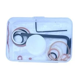
The NXWerks service kit for the Pistelle X-68 — includes all O-rings and grease.
| O-ring | Location | |
|---|---|---|
| Large O-ring #1 | Main valve body (same position if using a tuning chamber) | 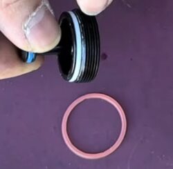 |
| Large O-ring #2 | Upper valve area | 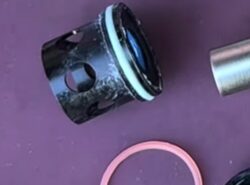 |
| Small O-ring | Top of the main valve (or tuning chamber) | 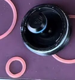 |
| Medium O-ring | CO₂ punch button | 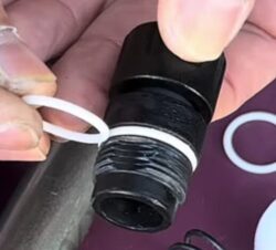 |
Official Manual
Just Saying
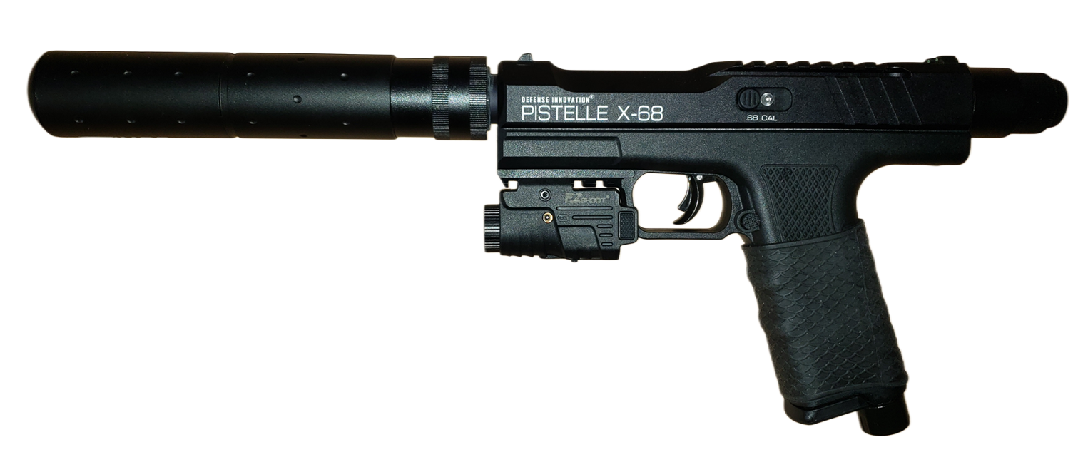
The Pistelle X-68 is a well-built, powerful launcher that’s fairly easy to maintain once you understand the O-ring layout and valve architecture. The most common leaks occur at the piston and bolt assembly — you’ll rarely need to go deeper than that.
Keep your O-rings greased, keep the pin oiled, and inspect the magazine tab regularly, and it will give you reliable performance for years.
For more on disassembly, reassembly, and O-rings, check out the amazing video tutorials from Modern Combat Sports, Less Lethal Home Defense, Less Lethal for Dummies, and Less Lethal Ballistics.